
-
Advantages
- Pressure-tight chamber for subterranean and above ground installation
- Flexible due to freely selectable inlets
- Large tank volume
- Surface coupling made of corrosion-resistant PUR
-
Technical Data
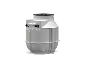
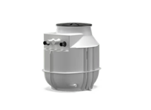
Design
Plastic chamber with pipework, for connecting one or two pumps. Suitable for underground installation or building installation.
Application
- As a lifting unit within buildings (above ground installation).
- As a pump chamber outside buildings (concealed floor installation).
- For backflow resistant drainage of
- Drainage points below the backflow level
- Drainage points that cannot be drained via the natural downward slope.
Equipment/function
- Gate valve
- Surface coupling with integrated non-return valve
Typekey
Example: DrainLift WS 40E DrainLift Product family WS Pump chamber 40 Size E Chamber design: - E = Single-pump system
- D = Double-pump system
Technical data
- Vessel volume: 255 l/67 US.liq.gal. (WS…E)/400 l/105 US.liq.gal. (WS…D)
- Maximum pressure in the discharge pipeline: 1.5 bar (22 psi)
- Discharge port: R 1½ (WS 40), R 2 (WS 50)
- Inlet connection: DN 100/150/200
- Ventilation connection: 75 mm (3 in)
- Fluid temperature: 3 … +40 °C (37 … 104 °F)
- Ambient temperature max.: 3 … 40 °C (37 … 104 °F)
Materials
- Pump chamber: PE
- Pipework: 1.4404 (AISI 316L)
- Stopcock: Red brass
- Non-return valve: PUR
Construction
Chamber
Pump chamber with optimised geometry for deposit-free operation. Chamber component with finning for high inherent stability and anti-buoyancy. The inlets are freely configurable. Two lifting eyes are integrated for attaching the lifting accessory. The upward curved pump chamber cover can be walked on and can be loaded with max. 200 kg. For the building installation, the pump chamber is equipped with a floor fixation.
Pipework
- Discharge pipe with flange connection on the pump side
- Gate valve
- Surface coupling
- Non-return ball valve (integrated in the surface coupling)
Configuration
- The pump chamber for two pumps has separate pipework for each pump. They therefore also have two discharge ports. Provide the Y-piece on-site.
- The maximum ground water level above the bottom edge of the chamber is 500 mm.
- Downloads
